-
Tel : +86 18148038996
-
Email : zhangwenying@yankong.com
Tel : +86 18148038996
Email : zhangwenying@yankong.com

Brand:
YakoItem no.:
YKD3722MPayment:
100% T/T payment before deliveryProduct origin:
Made in ChinaProduct weight:
2.3kgLead Time:
Normally 7 workdays
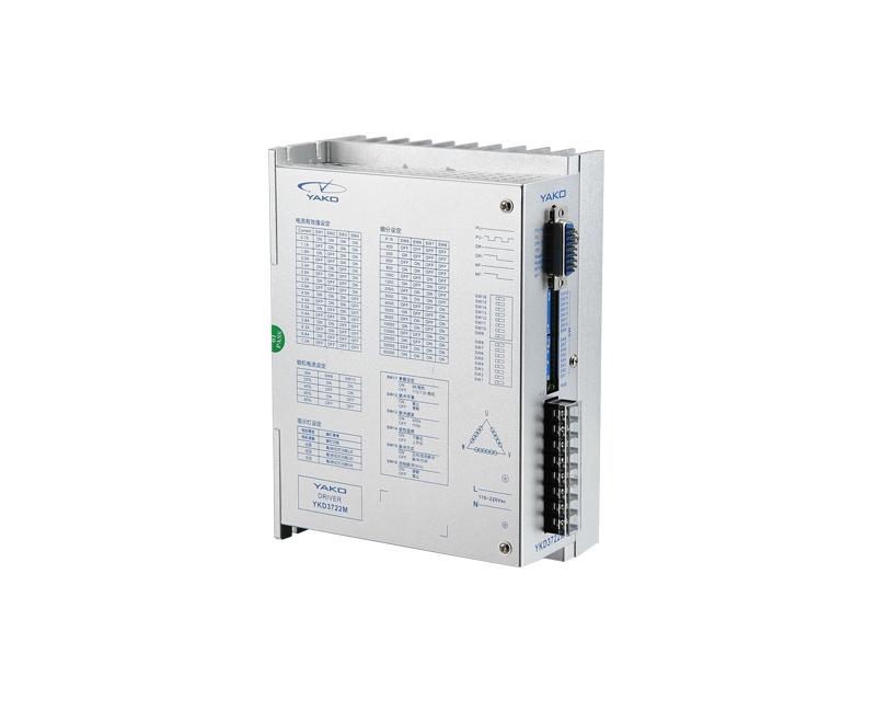
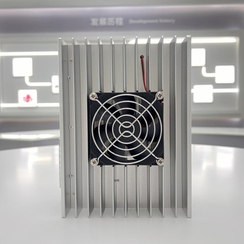
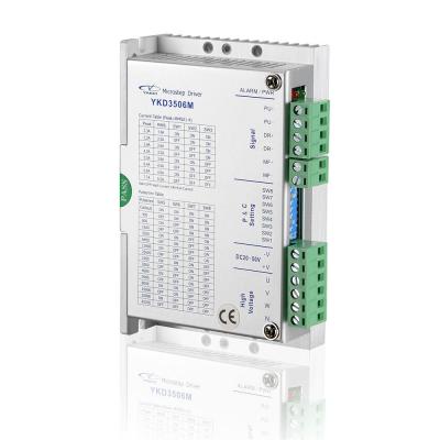
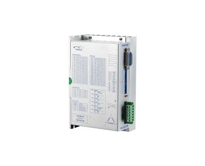
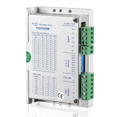
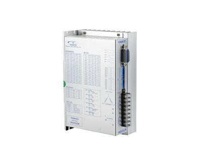
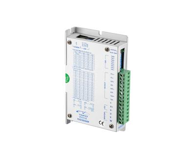
YKD3722M Yako 3 Phase Open-Loop Digital DSP Stepper Driver
It is suitable for three-phase stepper motors with a current below 7.0A. The flange size is 86-130mm. The drive uses a control technology similar to that of the servo. Unique circuit design and excellent software algorithm make the motor run smoothly under low microstep and ultra-low noise and vibration. Optically isolated differential signal input, strong anti-interference ability; with over-voltage, under-voltage, over-current protection functions.
Features:
Application:
Mainly used in laser cutting machine, laser welding machine, laser marking machine, locking screw machine, medical equipment, robot, dispensing machine, electronic equipment, engraving machine.

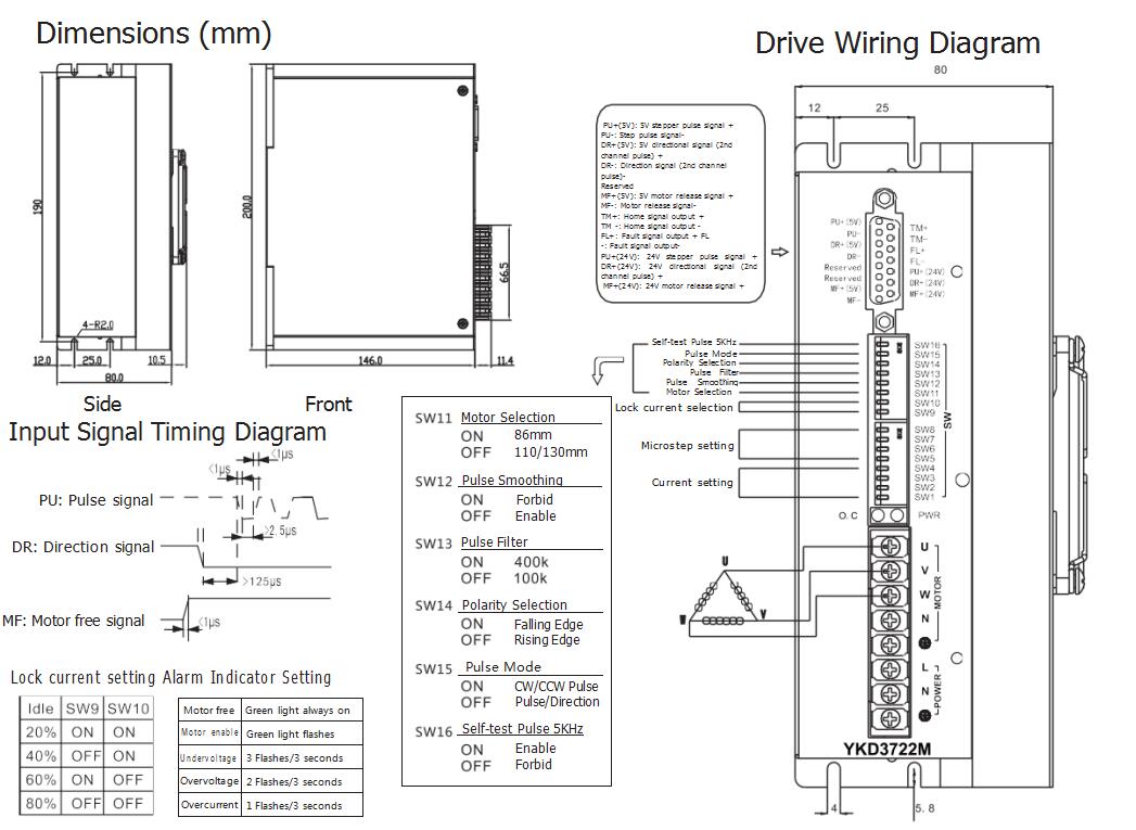
Dimensions
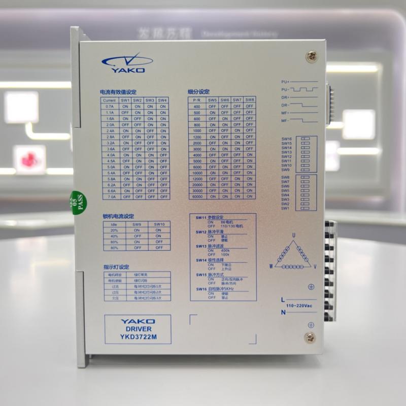
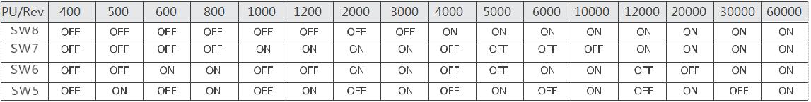
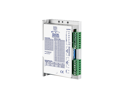
YKD3506M Microstep Setting
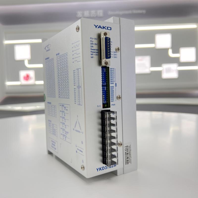
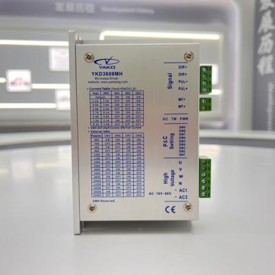
Terminal Introduction
|
Symbol |
Function |
Specification |
|
PWR |
Power indicator |
When power on, the green indicator lights up. |
|
O.C |
Fault indicator |
When over current, under voltage or over voltage, the red indicator lights up. |
|
PU+24V/5V |
Input signal + (24V/5V) |
Connect to 24V/5V power supply |
|
PU - |
SW15=ON, it’s CW pulse signal |
Effects on falling edge, the motor moves a step when pulse goes from high to l It requires: When connect with 5V PU+, low level 0~0.5V, high level 4~5V; wh connect with 24V PU+, low level 0~0.5V, high level 20~24V. Pulse width >2.5u effective edge can be selected by DP14 in pulse/direction control mode. |
|
SW15=OFF, it’s pulse signal |
||
|
DR+24V/5V |
Input signal + (24V/5V) |
Connect to 24V/5V power supply |
|
DR - |
SW15=ON, it’s CCW pulse signal |
Effects on falling edge, the motor moves a step when pulse goes from high to l It requires: When connect with 5V DR+, low level 0~0.5V, high level 4~5V; wh connect with 24V DR+, low level 0~0.5V, high level 20~24V. Pulse width >2.5u |
|
|
SW15=OFF, it’s direction control signal |
Used to change motor direction. It requires: When connect with 5V DR+, low level 0~0.5V, high level 4~5V; when connect with 24V DR+, low level 0~0.5V, high level 20~24V. |
|
MF+24V/5V |
Input signal + (24V/5V) |
Connect to 24V/5V signal power supply |
|
MF - |
Motor free signal - |
When effective (low level), the motor coil current is turned off and motor free |
|
FL + |
Fault output signal + |
FL+ connect to the output current limiting resistor |
|
FL - |
Fault output signal - |
FL- connect to the output GND, maximum drive current 50mA, and maximum voltage |
|
TM+/TM- |
Home output signal +/- |
TM+ connect with the resistor, TM- connect to output GND. Maximum driv current 50mA, and maximum voltage 50V. |
|
AC |
Power supply |
AC110- 220V |
|
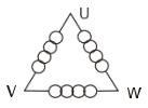
V |
Motor connection |
|
|
W |
||
|
N |
 English
 español